DS200PCCAG1A: Brainpower of MARK V DS 200

DS200PCCAG1A is a Capacitor Board designed by “GENERAL ELECTRIC Turbine and Excitation Controls.” It belongs to the series MARK V DS200 and is an essential part of the turbine. It controls the power supplied to the whole turbine. However, to understand the working of DS200PCCAG1A better, you need to understand the functions and working of Capacitor Boards.
The capacitor board is the most important electronic component in the circuit board or printed circuit board. It helps in saving energy by helping its discharge into the circuit. Also, it allows the Alternating current to pass while withholding the Direct current.
DS200PCCAG1A capacitor board
The DS200PCCAG1A meddles between the drive and the Silicone-Controlled Rectifier Bridge. For low to medium horsepower controllers, the DS200PCCAG1A also includes AC and DC snubber circuits. They are present to control the spikes, the AC lines, dc bus, and gate drivers. All these components contribute to the production of higher horsepower. Numerous snubber circuits are omitted to form the DS200PCCAG1A board and are located elsewhere on the system.
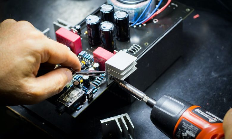
The state-of-the-art DS200PCCAG1A printed board has made up of different electronic components. It includes various microprocessors, capacitors, resistors, semiconductors, chips, pulse transformers, and input and output connectors for a stable connection. It is the best example of GE’s work in its design thought process.
DS200PCCAG1A also includes an RC snubber network to protect the Silicone-Controlled Rectifier. The snubbers connect across the SCR in the control core. The PCCA generates SCR firing pulses through its onboard pulse transformers. The PCCA connects to the DCFB via 5PL and each bridge SCR via 1FPL through 6FPL.
HOW TO IDENTIFY THE BOARD
The board will be identified by the alphanumeric part number stamped or printing on the edge. For example, the Power Connector Card is determines by the part number DS200PCCAG1A. SOPs to follow before replacing the board to ensure the replacement behaves the same as the old discarded one. Following the instructions will lead to the stand-in of this board replace quickly and provide less downtime.
Step 1
1st step includes a thorough inspection of the failed capacitor board and identifying the cause and failure component.
Step 2
2nd step is to note the jumper settings on the previously connected jumpers and switches and ensure that the replacement board functions at the same capacity as the original circuit board.
NOTE
In some cases, the newer version of the board will come with a different layout of the board and will not contain the same jumper, switches, etc. If this is the case, you can inspect the board and refer to the information that came with the board to understand how to make the new board behave like the old replaced one.
User discretion
The user must be wary of some necessary protocols and must operate accordingly.
First off, never remove the board or any connector parts while power is on for the drive. There should be no re-inserting in this situation as well.
The capacitor board contains potentially lethal voltage when powered. To prevent electric shock, turn off the power to the drive. Then reinsure that no authority exists on theboard before touching it or any connected circuits.
To replace the DS200PCCAG1A power connector board.
- Turn off the power to the drive to cut the power to the board. Wait several minutes for the discharge from all the capacitors.
- Open the cabinet door where the equipment board is present. It exposes the drive controller card, which faces the front.
- The PCCA board is mountes on the back of the board carrier behind the drive control (the power supply board is mounted on the front.
- Pull the lock tabs on either side of the board rack, lift the front board carrier and tilt it forward down.
- Lift the second board carrier (with the power supply board) and tilt it forward and down to access the PCCA board.
- Carefully disconnect all cables from the PCCA board as follows;
- For the ribbon cables, grasp each side of the connector that mates with the board connector and gently pull the cable connector free. For line with pull tabs, gently pull the pull tabs.
- Push back the six plastic holders to release the board from the board carrier.
- Please verify that all the jumpers on the new (replacement) PCCA board are in the same position as they were on the replaced board.


![Photo of How to solve [pii_email_f471d3ee8613f77bd6e2] and other Microsoft Outlook errors](https://keyposting.com/wp-content/uploads/2021/06/Microsoft-Outlook-errors-390x220.png)

